Progressive cavity pumps are widely used in various industries for their ability to handle viscous fluids and maintain a consistent flow rate. Understanding how to read a progressive cavity pump diagram is essential for effective operation and maintenance. This article will guide you through the key components and features of a typical diagram.
Key Components of a Progressive Cavity Pump
A progressive cavity pump diagram typically includes several crucial components. Familiarizing yourself with these elements will help you interpret the diagram accurately:
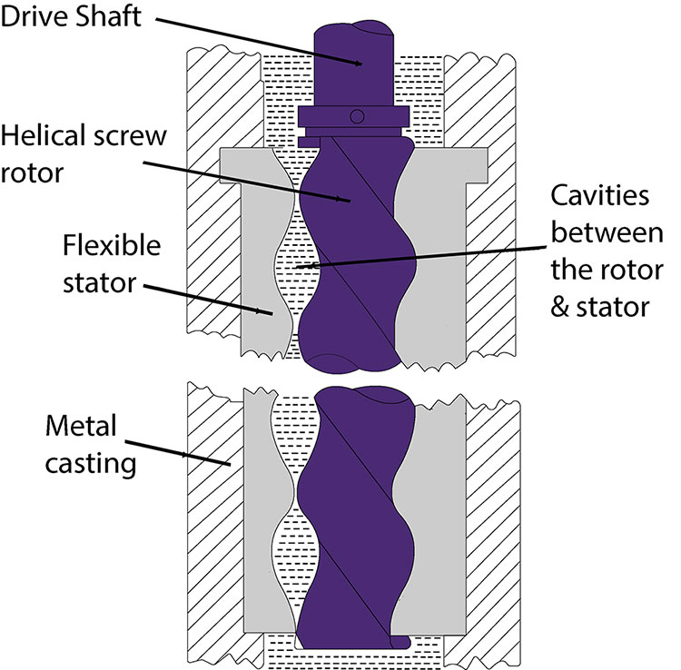
- Stator: The stationary part of the pump that houses the rotor. It is usually made of elastomeric materials to accommodate various fluids.
- Rotor: The rotating element that moves the fluid through the pump. It is designed to fit snugly within the stator.
- Inlet: The entry point for the fluid being pumped. It is often located at the bottom of the pump.
- Outlet: The exit point where the fluid is discharged. This is typically found at the top of the pump.
- Drive Shaft: The component connected to the rotor that converts mechanical energy into rotational motion.
- Bearings: Support the rotor and ensure smooth operation. They can be either lubricated or self-lubricating.
- Seals: Prevent leaks between the various components, ensuring the pump operates efficiently.
Understanding the Flow Path
The flow path in a progressive cavity pump is critical to its operation. The diagram illustrates how fluid moves through the pump:
- Fluid Entry: The fluid enters through the inlet and fills the cavities formed between the rotor and stator.
- Progressive Movement: As the rotor turns, it creates a progressive movement, pushing the fluid along the cavities toward the outlet.
- Fluid Discharge: The fluid exits the pump through the outlet, maintaining a consistent flow rate.

Diagram Features
When interpreting a progressive cavity pump diagram, pay attention to additional features that provide valuable information:
- Orientation: The orientation of the pump can affect its performance. Diagrams often indicate whether the pump is horizontal or vertical.
- Mounting Options: Diagrams may include various mounting configurations, which can influence installation and maintenance procedures.
- Flow Direction Arrows: Look for arrows indicating fluid flow direction, which is essential for understanding how the pump operates.
Maintenance Considerations
Regular maintenance is vital for the longevity of a progressive cavity pump. The diagram can help identify areas that require attention:
- Lubrication Points: Check the diagram for lubrication points on bearings and seals.
- Wear Indicators: Some diagrams indicate wear indicators that signal when parts need to be replaced.
- Service Access: Understanding the layout can help determine the best way to access components for maintenance.
Conclusion
Interpreting a progressive cavity pump diagram is a valuable skill for anyone involved in the operation or maintenance of these pumps. By familiarizing yourself with the key components, flow path, and diagram features, you can ensure optimal performance and longevity of the pump. Regular maintenance, guided by the diagram, will help prevent issues and enhance the efficiency of your pumping system.